|
|
!!!! P R E L I M I N A R Y !!!!! The extremly versatile Traffic Light Controller and more... A friend of me asked if I could make a traffic light controller for his HO model train. Of course I can make that, just a little microcontroller, some software, a circuit board etc. But, as usual, I could not resist and add a few more features. The result is a pretty universal controller that solves many lighting 'problems' that model train hobbyists often have. The end result is a board that has 6 programs:
Program 4 has three flipflop blinkers. I made them so that they all run at slightly different frequencies (adjustable) to get a more natural effect. It would spoil the effect if you had three blinkers on your train scenery that all go on and off at exactly the same pace. Program 6, the fire simulation uses three leds, all fading in and out at different frequencies. The idea it to use three leds, yellow, white or orange, or a mix, and create a very 'high fidelity' fire. Features of the board:
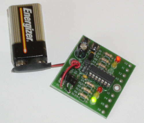
Here's a picture of the board:
In the top-left we see the two buttons. These are used to select the program or to set the speed. These setting are all stored inside the microcontroller, and remain stored, even when power is off. In the middle you see three jumpers. Placing the jumper in position 1 allows you to select the program by pressing the up/down buttons. The selection is shown by one of the six leds. When you remove the jumper, the buttons allow you to control the speed. Press up for faster, down for slower. The speed is automatically stored in the memory. Placing the jumper in the 2nd position, tells the microprocessor to behave differently, depending on the program. For instance, when the traffic light program is chosen, it will make the yellow lights blink. You could solder some wires to these pins and run them through a switch. Placing the jumper in the 3rd position, inverts all outputs. This may be useful if you have traffic lights with leds that are connected to ground, i.e. all cathodes of the leds go to ground. In most case however, the leds have all their anodes connected to plus, and you won't need this jumper. The board has connections for the external leds. The leds on the board are only for convenience. The power input has a bridge rectifier. This means you can run the board on DC or AC. Polarity is not important. The board also has a regulator for the microcontroller, so you have a wide choice for input voltage. Anything between 9-16V, AC or DC is just fine. The outputs can deliver 20mA maximum. This is plenty for leds. Small leds, such as used in model trains, are 1-3mm and only need a few mA (5?). If you want to connect many leds, try to find high efficiency leds, these are quite happy with 2-3mA. To calculate the resistor value for each led, divide 3 by the number of milliamps. If you have a 3mA led, a 1Kohm resistor is fine. The board has series resistors of 470 ohms. If need be, you can replace these with a lower value of 180 and use external resistors to each led. The board is double sided and measures roughly 48mm x 48mm. That's a little less than 2 inch x 2 inch. It has two holes for mounting screws, so you easily mount it somewhere under the table with simple wood screws. I don't have kits or assembled modules yet. I don't know if there is a market for these kind of modules. Drop me an email if you are interested. If I get some responses, I probably make this design available as a kit or fully assembled. Last updated 18 Sep 2004
|