|
|
I like clocks. It's as simple as that. Quite a while ago I saw a binary clock, and I like it instantly. Six rows of four leds, representing the time in a binary format. It takes some time to get used it, but after a couple of days it reads as easily as any ordinary clock. The first days you have to add the binary values, but after a while you simply look at the patterns and 'know' the time. There are already kits on the market for these kind of clocks. You can also buy them as consumer items, in specialized gift shops. Since I like to design stuff, I rolled my own binary clock. One of the reasons was that I could add the backup function that keeps it running while power is lost. Not many 'on the shelf' clocks have a backup function, so that seems a valid reason to make one yourself. I added some animation features for the display, to make it look more fascinating. There are 6 different animation modes. For this clock I picked a recent member of the PIC processor family. I didn't need many output pins, and the PIC16F87 is the perfect fit for this job. It has plenty program space too. In the end I preferred the PIC16F88. It's the same as the 16F87 but the inputs can also be used as analog inputs. While in this design there is no need for analog inputs, I choosed the 16F88 just in case I get some ideas for another kit that may need analog inputs. The price difference between the two is really small, so there is no reason to go with the less equipped 16F87.
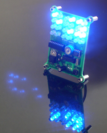
This is how it looks. Not bad eh? IC1 is on the left, it is the processor. It is clocked by oscillator IC103, the one below the supercap, ticking away at no less than 18.1818MHz. C109 is a supercap that powers the realtime clock chip IC104, the backup option. The realtime clock runs on a 32.768KHz crystal. On the left there is a simple 5V regulator. The setting of the clock is done with a single switch S1, the little switch in the righthand bottom corner. If you have build one of my nixie clocks, you know how easy it is to set the clock with just one single button. To give this clock a higher 'Geek' factor, the leds also make all kinds of animated patterns, if desired. Color of the leds? Pick from the available colors, but blue is very nice!
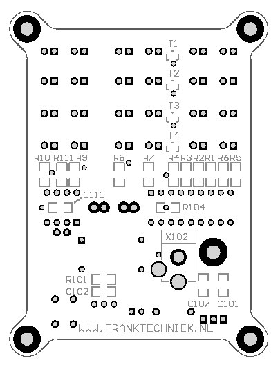
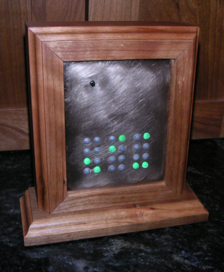
Here's a drawing of the other side of the board. Yes, the board is double sided and some components are mounted on the back. While they are SMD components, it's not too difficult to mount these. If you have some soldering experience, you will do fine if you follow the guidelines in the assembly instructions. On the other hand, if you have never soldered anything before, you should ask for some assistance. The board measures roughly 66mm x 88mm. It has four holes for mounting screws, so you easily mount it somewhere behind a plexiglass stand or something. The kit can be ordered in my web shop. Also consider the RTC option. I tried to keep the price as low as possible, but making kits in these very low quantities does not allow for a really low price. Here's a nice example of the clock, made by Rex. He has an impressive workshop with a lot of tools, including a CNC controlled mill. And a master in woodwork as well. He has turned the board upside down, probably mounting the leds on the backside. I have no idea how late it is on his clock. That is his secret.
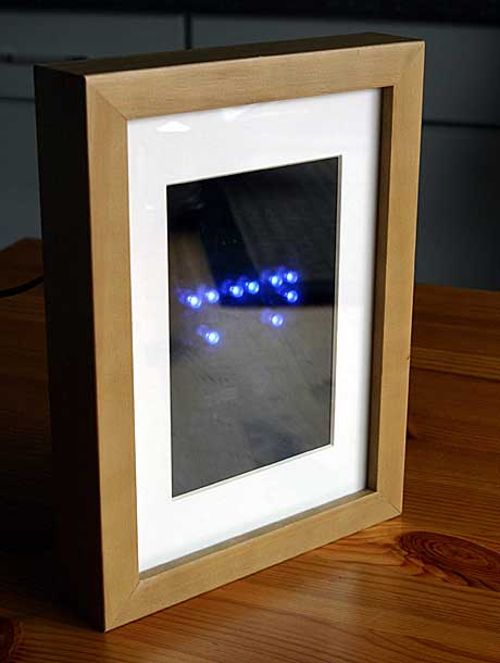
Another excellent example can be seen here, it's made by Michael. The approach is simpel and clever and gives a stunning result. A frame, a passe-partout, and a piece of smoked plexiglass behind the passe-partout.
More details and pictures of this clock can be found on Michael's website. Files for the Binary Clock project:
List of Binary Clock Owners
Last updated 14 feb 2005
|