|
|
|
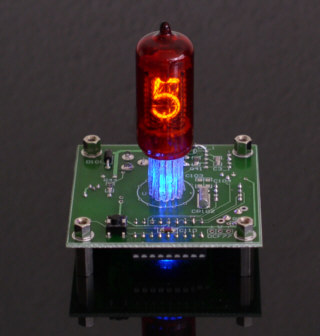
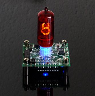
Nixie Clock Z570M-1-V1 The electronics for this clock are based upon the succesful CD81-6-V3 but this clock uses only one single tube. The tube used here is a Z570M and a bit larger. Total dimensions of the prototype (!) clock are are 59mm x 59mm x 74mm (WxHxD). The final version was made a bit smaller, and has a board size of only 51mm x 51mm (2" x 2"). That may not look as a big difference, but the area is 25% smaller. The prototype is in the picture below. The wires of the tube are isolated with transparent sleeve with little sparkles in it. Underneath the nixie tube sits a LED which can be turned on or off, work as AM/PM indicator, or even work as a signal indicator for a atomic time receiver.
The power supply for this clock is just a simple 12VDC adapter. If you don't have a spare one, you can find one locally, or order one from my webshop. The board also has place for RTC option and connections for a DCF77 time receiver (Europe) or a WWVB time receiver (USA). The software automatically recognizes both these protocols. The software provides some useful options, such as 12hr/24hr time format, calibration of the clock oscillator, various modes for the center LED etc. All settings are done with one single pushbutton.
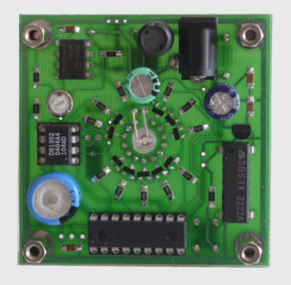
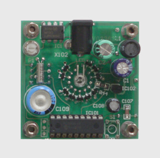
Here's a picture showing the electronic heart of the clock. In the top-left corner you can see the HV generator that converts 12V into a regulated supply for the nixie tubes, adjustable up to 180V. The PIC microcontroller is fitted on the bottom side of the PCB. On the right, there's the 5V regulator and oscillator. On the left we have the RTC components, such as the Dallas DS1302, a 32.768 KHz crystal and a SuperCap. The SuperCap enables the clock to keep the time for about a week without external power. The bottom side has a silkscreen now, which makes it a lot easier to mount the components in the right place and right orientation. Be warned that this clock uses a fair amount of small smd components and therefore not recommended if you have never soldered before. On the other hand, you don't need to have experience with smd components. I choosed relative large 1208 size smd components and these are not too difficult to handle. If you can solder a 25 pole d-connector without too much trouble, you are skilled enough for this kit. You can order the kit in my web shop. Special version of Z570M-1-V1
Files for Z570M-1-V1
Picture Gallery of Nixie Z570M-1-V1
|