|
|
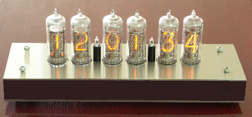
Nixie Clock IN14-6-Vx The electronics for this clock are practically the same as for the CD81-6-V3 but since the tubes are larger, the board is also larger. All the components are placed on one single board. Dimensions are 210mm x 75mm x 72mm (WxHxD).
The power supply for this clock is just a simple 12VDC adapter. You probably have a spare one, or you can find one locally. This board also has place for RTC option and connections for a DCF77 time receiver. It has place to fit the extra RTC components and a voltage dropper for particular DCF77 modules that run on lower voltages. Check the schematics to see how it's done, there are some instructions there as well.
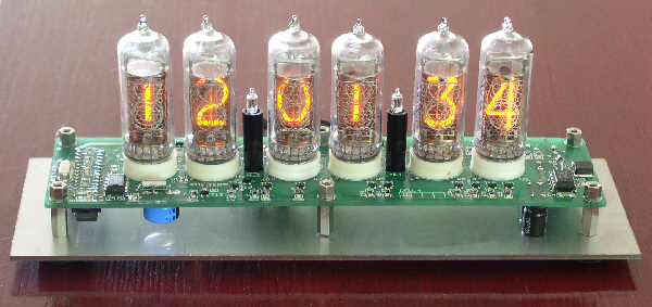
Okay, here's another picture showing the electronic heart of the clock. At the righthand side you can see the HV generator that converts 12V into a regulated 142V, the supply for the nixie tubes. The PIC microcontroller is fitted on the bottom side of the PCB, together with a 5V regulator. You can also see the RTC components, in front of the first tube, the Dallas DS1302, a 32.768 KHz crystal and the SuperCap, which is on the bottom. Be warned that this clock uses a fair amount of small smd components and therefore is not a kit for beginners!!!! Also, this clock needs a 12VDC/300mA adapter which is not included. You can find the kit in my web shop. You can also order a partial kit. All order numbers start with IN14-6-Vx, where x is just the revision number. Current version is V2, which has the (optional) leds wired differently, now with constant power applied. It's not significantly different from V1. Files for Nixie Clock IN14-6-V1
Files for Nixie Clock IN14-6-V2 Anti Ghosting Modification for Nixie Clock IN14-6-V2
List of Nixie Clock IN14-6-V1 Owners
List of Nixie Clock IN14-6-V2 Owners
That's it folks, soldout for now... Last updated 15 Nov 2005
|